O2 BoatA 70 cm radio-controlled jet boat that has to throw water 60 cm onto a target. I owned the electronics and the code that drives them.
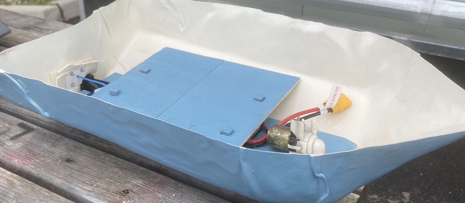
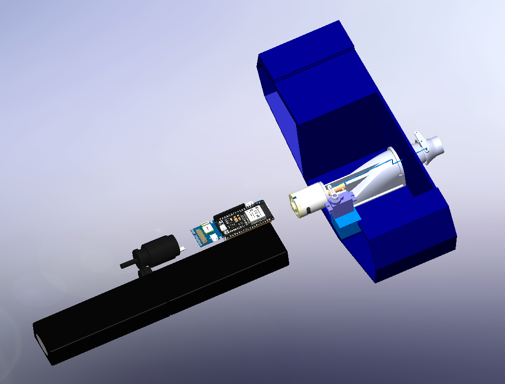
A previous team designed it on paper. Ours had to prove it would actually work.
Semester one was a series of sprints: validate or replace every choice made the year before, function by function. Buoyancy, movement, water throw, control. Semester two, build it.
Hull wall 1 cm → 0.3 cm and a smaller footprint to hit 70 cm. Lighter roof with a ledge to keep water out.
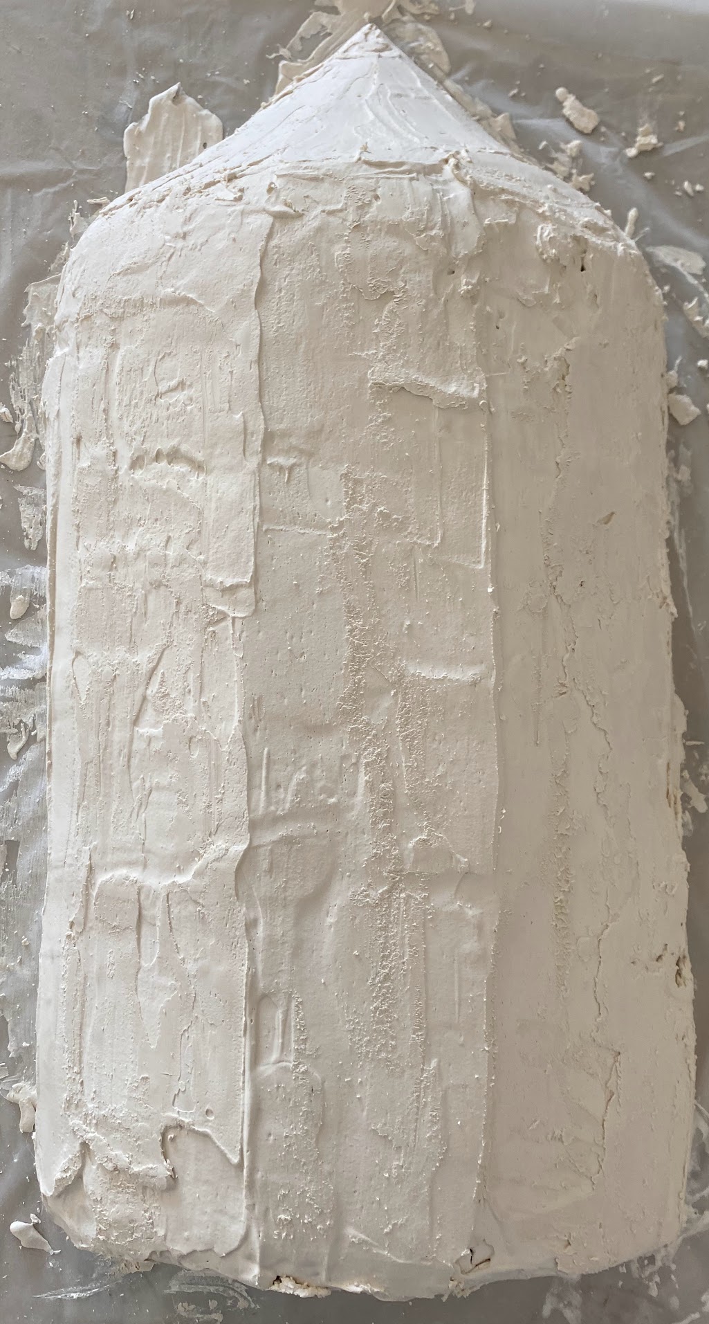
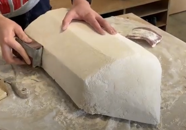
The V-hull with a flood chamber: air-filled upright, it floods when capsized and rolls the boat back.
7.5 kg of margin before the hull sinks. The catch was lateral: the flood chamber puts 2.31 kg on one side against 1.31 kg on the other, so components and a 1 kg ballast go to port to keep the boat level under way.
Power and propulsion
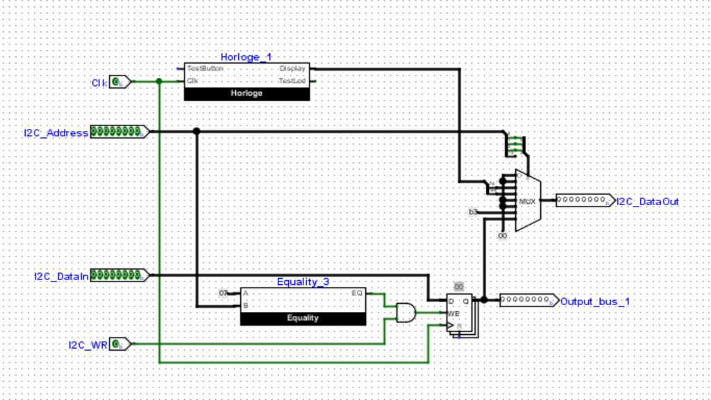
- 12 V · 12 Ah battery feeding an L298 H-bridge for speed and reverse.
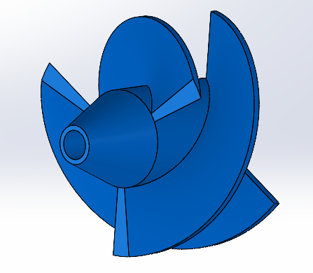
- A jet needs revs, not torque: a small, fast JYCRS390H 12 V brushed motor driving a 3D-printed impeller.
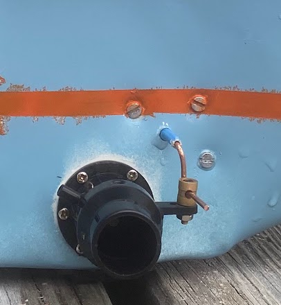
- Servo on the nozzle for steering; current sensor and compass on the bus.
Three brains
- ESP32 hosts the Wi-Fi web interface: speed, battery, link status, start/stop.
- Arduino MKR + Vidor: the Vidor’s FPGA decodes the radio receiver in hardware.
- Mode selection: phone, remote or autopilot, the remote taking over past ~100 m when the phone signal drops.
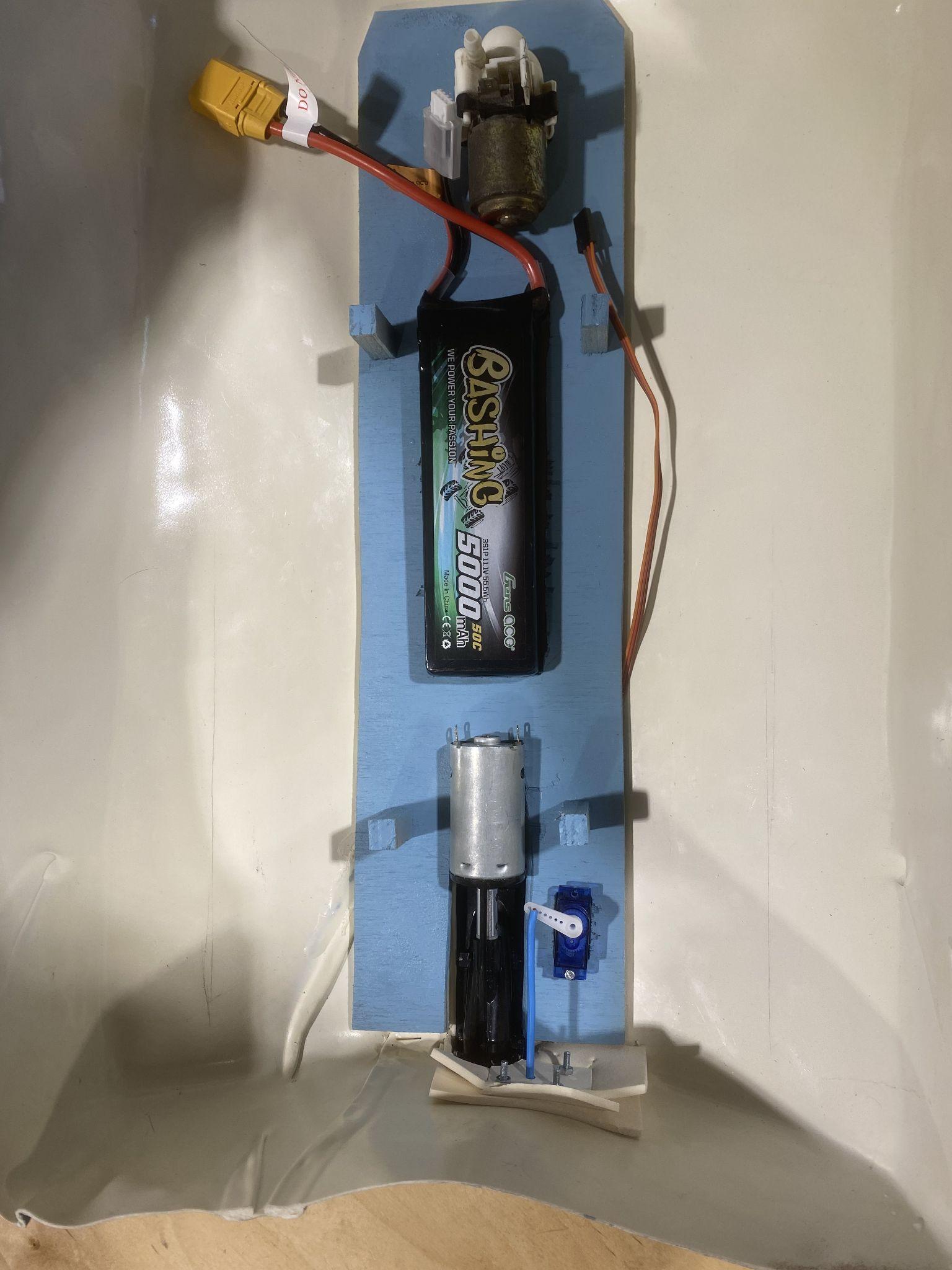
The receiver outputs a pulse between 1 and 2 ms. I wanted 8-bit resolution over that window, so 256 counts in 2 ms.
Steering band read from the counter value.
Same bands select the pilot: phone, remote, autopilot.
Above 64 on the throttle channel: speed up. Below: slow down.
Two kinds of code. A web page served by the ESP32 over its own Wi-Fi, so any phone becomes the console; and hardware logic drawn in Logisim for the FPGA, so decoding the radio pulses costs the microcontroller nothing.
- Interface first. HTML / CSS / JS page written and tested on a reference board: start, stop, speed, battery, Wi-Fi and radio link status. Then moved to the Arduino IDE and wired to the boat’s own sensors.
- Who is in charge. The ESP32 pings the phone every second. No answer past ~100 m and control hands over to the radio remote; the FPGA switches the mode.
- Pulse to number. A ÷547 divider, a 256-step counter built from four 4-bit counters, and a comparator. One byte per channel, no interrupts, no jitter.
// ESP32 · who drives the boat
void loop() {
  if (millis() - lastPing > 1000) {
    phoneAlive = server.ping(phone);   // 1 Hz heartbeat
    lastPing   = millis();
  }
  mode = phoneAlive ? PHONE : REMOTE;   // remote past ~100 m
  fpga.select(mode);                    // 128–170 · 170–212 · 212–256

  int throttle = fpga.count(CH_THROTTLE);
  hbridge.drive(throttle > 64 ? FASTER : SLOWER);
  nozzle.write(bandToAngle(fpga.count(CH_STEER)));

  ui.send(speed, battery, mode);        // live telemetry to the web page
}