DELIVERWHOA two-wheeled delivery robot for the campus. No kickstand, no third wheel: it stays upright because the code says so.
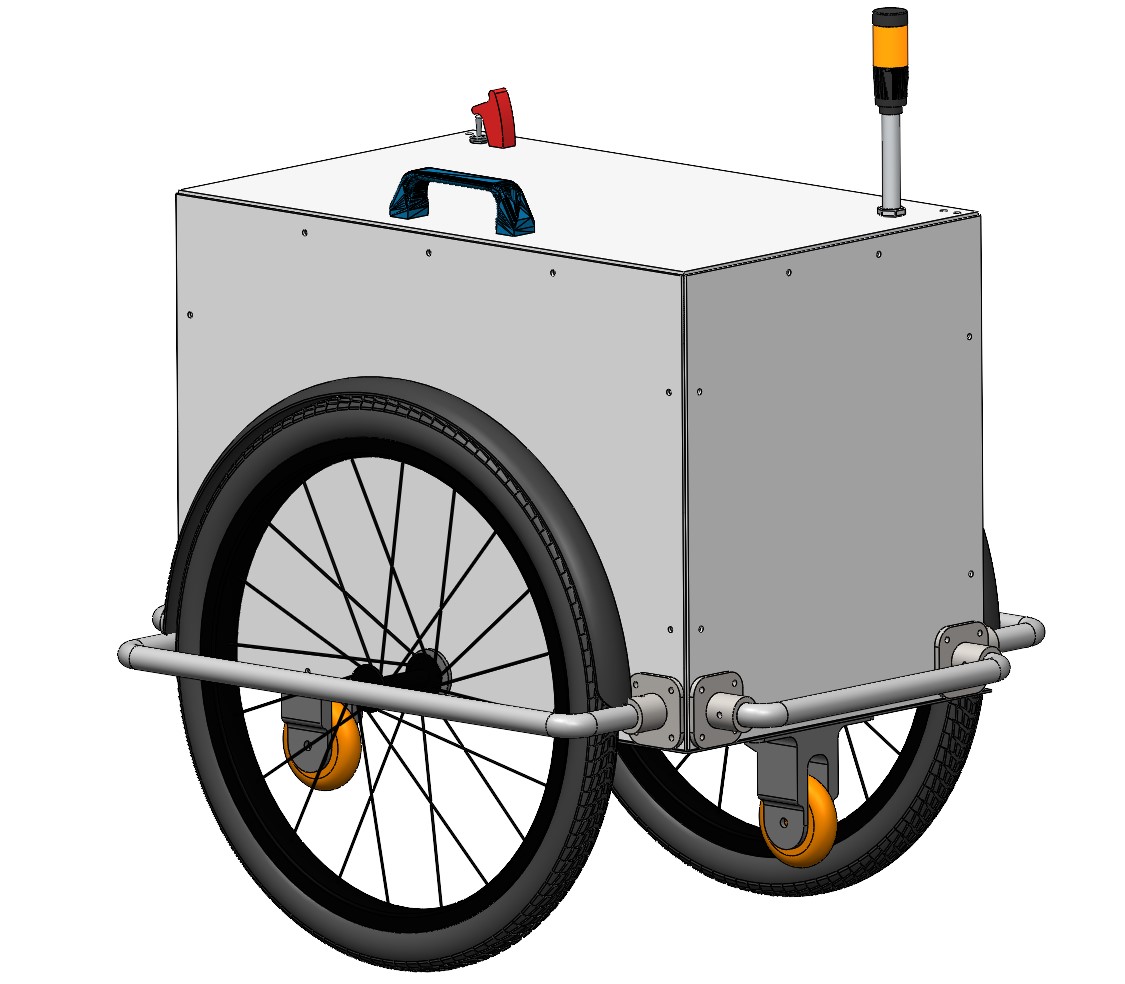
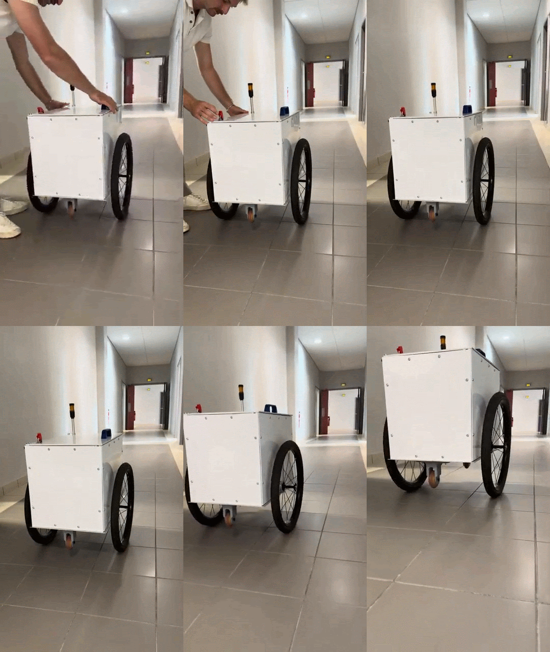
Parcels on campus were hand-delivered. The volume kept growing; the people didn’t.
The robot has to cross indoor and outdoor ground, fit through standard doors and lifts, carry a 5 kg parcel and run two hours. Two driven wheels keep it compact and agile, and turn balance into the central engineering problem.
The maths of balance and locomotion, the Simulink digital twin, then the C++ control firmware and the controller interface, with Erwan on the code.
ISO 13482 (personal-care robots), 9001, 14001, 45001.
Chosen: a 57BLR50-24-01 brushless motor (84 W, 24 V, 0.23 N·m at 3500 rpm) behind a 10:1 MG23-G10-D8 gearbox, so 2.3 N·m at 350 rpm with a 400 N load rating.
Tune the loops on the model, then port them to the metal.
A multibody model of chassis, wheels and centre of gravity, with two PID loops: one holds the tilt angle, the other the travel speed. Gains were tuned by hand until a simulated push returned to equilibrium quickly, with low steady-state error and controlled overshoot.
Continuous tilt control, setpoint driven by the user.
Active only within ±2° of the setpoint to kill micro-oscillations.
One reliable angle
MPU-6050 IMU fused with a complementary filter, 98 % gyroscope / 2 % accelerometer. Auto-calibration at boot averages 1 000 samples.
Two drivers, one sign
BLD-4055 brushless drivers under PWM, polarity flipped with the direction of travel. The robot takes small pushes and rights itself.
A PS5 controller
DualSense over Bluetooth. Left stick sets the tilt setpoint, right stick spins in place, ✕ toggles stabilisation, △ recalibrates the gyro. ±12 deadband on both sticks.
The Simulink block diagram became a single C++ loop on the ESP32. Read the IMU, fuse it into one angle, run the right PID, write PWM to both drivers, handle the controller. Same structure as the model, so the gains transferred with only re-tuning.
- Two PIDs, one output. The main loop tracks the tilt setpoint; inside ±2° a softer fine loop takes over so the robot stops hunting.
- Filter before control. The gyro integrates cleanly but drifts; the accelerometer is noisy but absolute. 98 / 2 keeps the best of both.
- Calibrate every boot. 1 000 samples averaged on the ground so the zero angle is the real zero.
- Deadbands and toggles. ±12 on the sticks; ✕ disarms the loop, △ recalibrates.
// simplified from the ESP32 firmware
void loop() {
  float gyro  = mpu.gyroX() * dt;
  float accel = atan2(mpu.accY(), mpu.accZ());
  angle = 0.98 * (angle + gyro) + 0.02 * accel;

  float target = map(ps5.LStickY(), deadband 12);
  float err = target - angle;
  float out = fabs(err) < 2.0
    ? finePID.step(err)   // P 3.0  I 0    D 0.12
    : mainPID.step(err);  // P 10.0 I 0.4  D 1.5

  float turn = map(ps5.RStickX(), deadband 12);
  driveL.pwm(out + turn);  // BLD-4055, sign = direction
  driveR.pwm(out - turn);

  if (ps5.Cross())    stabilise = !stabilise;
  if (ps5.Triangle()) calibrate(1000);
}
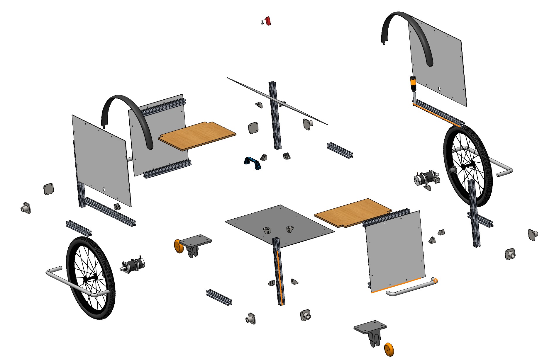
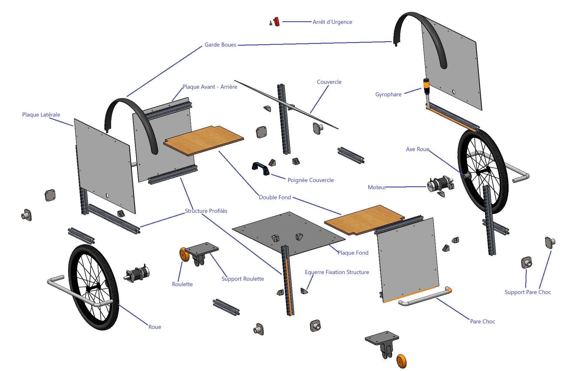
- 3 mm steel motor bracket checked by finite elements: Von Mises stress, displacement and strain under the drive loads.
- Aluminium profiles and ABS plates, chosen for weight, stiffness and quick disassembly.
- 3D-printed caster supports costed with SolidWorks Costing on the Fablab’s parameters: €17.02 per part.
- €500 held by reusing last year’s battery, wheel axles, wheels and motors.
KiCad board to replace the breadboard prototype.
Obstacle detection and indoor SLAM.
Routing between buildings.
And the full electrical integration in CAD.